


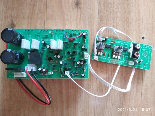
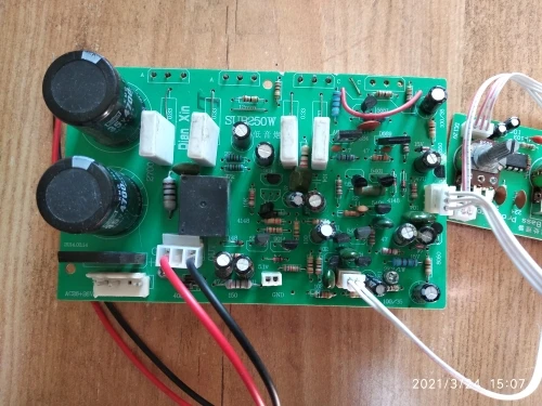
Photos of buyers
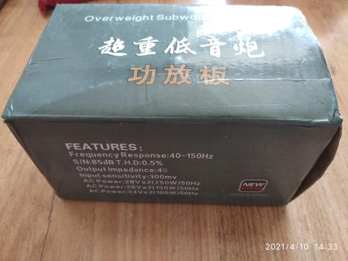
Specifications
- Brand Name: Tenghong
- Maximum Power Per Channel: Above 200W
- Model Number: Tenghong-H095
- Package: Yes
- Channels: 1
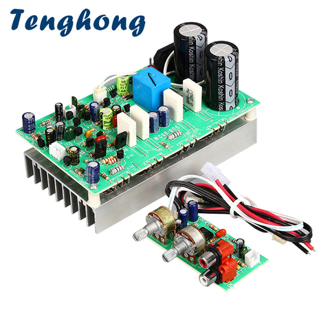
Tenghong Subwoofer Amplifier Board 250W Mono Sound Amplifier Power Audio Amplificador Board Home Speaker DIY Amp Dual AC22-26V
Price history
- for 3 month
- for half a year
- Requires Alitools extension
Price drop notification
This item is from other sellers


Similar Products
Customer Reviews
The board with the 2 knobs is to be panel mount. Now the design of the board is parallel nor perpendicular to the panel. There is no screw for the knobs (diameter 7 ....not standard) , and some components ( 100µf * 2 ) are two high for the panel to be in contact with knob/cinch input. The two connectors (power supply and signal output) have no place between the panel and the board ( 12 mm).... Only solution ....to unsolder these components and to resolder on the others side of the PCB. For the main board , a female connector will be welcome also for the power supply (2 * 26v)
The board with the 2 knobs is to be panel mount. Now the design of the board is parallel nor perpendicular to the panel. There is no screw for the knobs (diameter 7 ....not standard) , and some components ( 100µf * 2 ) are two high for the panel to be in contact with knob/cinch input. The two connectors (power supply and signal output) have no place between the panel and the board ( 12 mm).... Only solution ....to unsolder these components and to resolder on the others side of the PCB. For the main board , a female connector will be welcome also for the power supply (2 * 26v)