FM Radio Module Receiver Module PLL LCD Stereo Digital FM Radio Wireless Stereo Board LCD Display Noise Reduction 87-108MHz
Price history
- for 3 month
- for half a year
- Requires Alitools extension
Price drop notification
This item is from other sellers
Similar Products
Customer Reviews
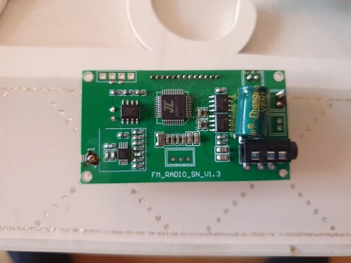
Visually, practically identical to the pictures. The majority of the pads on the board are readily understood, as well, save for a couple of glaring omissions. First off, while most of the pads say what their function is, it doesn't say how they're supposed to be activated. Are you supposed to attach a button that pulls them down to GND? Or pull them up the the power supply? Secondly, the serial control scheme isn't explained at all. I do understand that it can be plugged into a USB port (and I will be experimenting with that at some point), but the RX and TX pins don't have any information like number of bits used, any stop bits, parity, baud rates, etc.
Visually, practically identical to the pictures. The majority of the pads on the board are readily understood, as well, save for a rather glaring omission. Nowhere online have I been able to figure out how to interface with the Serial Control pads, marked RX,GND,TX. The chip's specifications list the relevant pins as "General Purpose I/O", and thus doesn't have anything to say about them. Nobody else appears to have explained how to use these pins, either, so I'm extremely curious what capabilities they allow.


